Iranian Classification Society Rules

< Previous | Contents | Next >
Section 2 Structural Requirements for Polar Class Ships
201. Application
1. These requirements are to be applied to ships of polar class mentioned in Sec 1.
202.
Ice strengthening regions
1. The ice strengthening regions of all polar class ships is divided into regions reflecting the magni- tude of the loads that are expected to act upon them. In the longitudinal direction, there are four regions: Bow, Bow Intermediate, Midbody and Stern. The Bow Intermediate, Midbody and Stern regions are further divided in the vertical direction into the Bottom, Lower and Icebelt regions. The extent of each ice strengthening region is illustrated in Fig 2.1.
2. The upper ice waterline (UIWL) and lower ice waterline(LIWL) are as defined in 103. 1.
3. Fig 2.1 notwithstanding, at no time is the boundary between the Bow and Bow Intermediate re- gions to be forward of the intersection point of the line of the stem and the ship baseline.
4. Fig 2.1 notwithstanding, the aft boundary of the Bow region need not be more than 0.45 L aft of the forward perpendicular (FP).
5. The boundary between the bottom and lower regions is to be taken at the point where the shell is inclined 7° from horizontal.
6. If a ship is intended to operate astern in ice regions, the aft section of ships ing the Bow and Bow Intermediate ice strengthening region requirements.
is to be designed us-
![]()
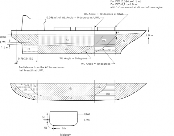
Fig 2.1 Ice strengthening region extents
203. Design ice loads
1. General
(1) For ships in all Polar Classes, a glancing impact on the bow is the design scenario for de- termining the scantlings required to resist ice loads.
(2) The design ice load is characterized by an average pressure( ) uniformly distributed over a rectangular load patch of height( ) and width(
(3) Within the Bow region of all polar classes and within the Bow Intermediate ice strengthening region of polar classes PC6 and PC7, the ice load parameters( , and ) are functions of the actual bow shape. To determine the ice load parameters, it is required to calculate the fol- lowing ice load characteristics for sub-region of the bow region; shape coefficient ( ), total glancing impact force ( ), line load ( ) and pressure ( ).
(4) In other ice‐strengthened regions the ice load parameters ( , and ) are de- termined independently of the hull shape. Accordingly, calculation of the glancing impact force
( ) and line load ( ) are based on a standard hull shape coefficient ( ) fixed load patch aspect ratio (
(5) Design ice forces calculated according to 203. 2 are only valid for ships with icebreaking forms. Design ice forces for any other bow forms are to be specially considered by the Society.
(6) Ship structures that are not directly subjected to ice loads may still experience inertial loads of stowed cargo and equipment resulting from ship/ice interaction. These inertial loads, based on
accelerations determined by the Society, structures.
2. Glancing impact load characteristics
The parameters defining the glancing impact listed in Table 2.2.
are to be considered in the design of these ship
load characteristics are reflected in the Class Factors
![]()
Table 2.2 Class factors
Polar Class | Crushing Failure Class Factor ( ) | Flexural Failure Class Factor ( ) | Load Patch Dimensions Class Factor ( ) | Displacement Class Factor ( ) | Longitudinal Strength Class Factor ( ) |
PC1 | 17.69 | 68.60 | 2.01 | 250 | 7.46 |
PC2 | 9.89 | 46.80 | 1.75 | 210 | 5.46 |
PC3 | 6.06 | 21.17 | 1.53 | 180 | 4.17 |
PC4 | 4.50 | 13.48 | 1.42 | 130 | 3.15 |
PC5 | 3.10 | 9.00 | 1.31 | 70 | 2.50 |
PC6 | 2.40 | 5.49 | 1.17 | 40 | 2.37 |
PC7 | 1.80 | 4.06 | 1.11 | 22 | 1.81 |
(1) Bow region
(A) In the Bow region, the force ( ), line load ( ), pressure ( ) and load patch aspect ratio
( ) associated with the glancing impact
load scenario are functions of the hull angles
measured at the upper ice waterline. The influence of the hull angles is captured through
calculation of a bow shape coefficient ( ).
(B) The waterline length of the bow region is
The hull angles are defined in Fig 2.2. generally to be divided into 4 sub-regions of pressure ( ) and load patch aspect ratio ( )
are to be calculated with respect to the mid-length position of each sub-region (each
imum of F, Q and P is to be used in the calculation of the ice load parameters
).
(C) The Bow region load characteristics are determined as follows:
(a) Shape coefficient, , is to be taken
as
where
max-
′
× s′ in × ×
= sub-region considered
= ship length as defined in Ch 1, 102. of the Rules but measured on the up- per ice waterline (UIWL) (m)
= distance from the forward perpendicular (FP) to station under consideration (m)
= waterline angle (deg), see Fig 2.2
= normal frame angle (deg), see Fig 2.2
′
= ship displacement (kt), not to be taken less than 5 kt
= crushing failure class factor from Table 2.2
= flexural failure class factor from Table 2.2
![]()
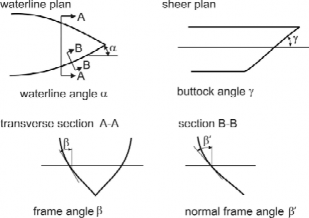
Note:
′
= normal frame angle at upper ice waterline [deg]
= upper ice waterline angle [deg]
= buttock angle at upper ice waterline (angle of buttock line measured from vertical) [deg]
tan tan tan
Fig 2.2 Definition of hull angles
(b) Force,
× × (MN)
where
= sub-region considered
= shape coefficient at of sub-region
= crushing failure class factor from Table 2.2
= ship displacement (kt), where
(c) Load patch aspect ratio,
min
5 kt
× sin′ ≥
where
= sub-region considered
′ = normal frame angle of sub-region
(d) (deg) Line load,
× (MN/m)
where
= sub-region considered
= force of sub-region (MN)
(e)
= load patch dimensions class factor from Table 2.2
= load patch aspect ratio of sub-region Pressure,
![]()
× × (MPa)
where
= sub-region considered
= force of sub-region (MN)
= load patch dimensions class factor from Table 2.2
= load patch aspect ratio of sub-region
(2) Ice strengthening regions other than the bow
(A) In the ice strengthening regions other than the bow, the force ( ) and line load ( ) used in the determination of the load patch dimensions ( , and de- sign pressure ( are determined as follows:
(a) Force,
× ×
where
= crushing failure class factor from Table 2.2
= ship displacement factor
=
if ≤
= if
= ship displacement (kt), not to be taken less than 10 kt
= displacement class factor from Table 2.2
(b) Line Load,
× × (MN/m)
where
3. Design load patch
= force from Equation 9 (MN)
= load patch dimensions class factor from Table 2.2
(1) In the Bow region, and the Bow Intermediate ice strengthening regions for ships with class no-
tation PC6 and PC7, the design load patch has dimensions of width, fined as follows:
, and height,
de-
(m)
(m)
where
= maximum force in the Bow region from Eq. 2 (C) (b) (MN)
= maximum line load in the Bow region from Eq. 2 (C) (d) (MN/m)
= maximum pressure in the Bow region from Eq. 2 (C) (e) (MPa)
(2) In ice strengthening regions other than those covered by (1), the design load patch has di- mensions of width, , and height, bNonBow, defined as follows:
(m)
![]()
(m)
where
= force determined using Equation 9 (MN)
= line load determined using Equation 10 (MN/m)
4. Pressure within the design load patch
(1) The average pressure, within a design load patch is determined as follows:
× (MPa)
where
= or as appropriate for the ice strengthening region under consideration (MN)
or as appropriate for the ice strengthening region under consideration (m)
or as appropriate for the ice strengthening region under consideration (m)
(2) Regions of higher, concentrated pressure exist within the load patch. In general, smaller regions
have higher local pressures. Accordingly, the peak pressure factors listed in to account for the pressure concentration on localized structural members.
Table 2.3 are used
Table 2.3 Peak pressure factors
Structural Member | Peak Pressure Factor ( | ) | ||
Plating | Transversely‐Framed | ≥ | ||
Longitudinally‐Framed | × ≥ | |||
Frames in Transverse Framing Systems | With Stringers | ≥ | ||
No Stringers | ≥ | |||
Stringers Side and Bottom Longitudinals Web Frames | i f if | ≥ × | × × | |
where, = frame or longitudinal spacing (m) = web frame spacing (m) = ice load patch width (m) | ||||
5. Ice strengthening region factors
(1) Associated with each ice strengthening region is an region Factor that reflects the relative mag-
nitude of the load expected in that region. The region Factor ( ) for each
region is listed in Table 2.4.
ice strengthening
(2) In the event that a structural member spans across the boundary of a ice strengthening region, the largest ice strengthening region factor is to be used in the scantling determination of the member.
(3) Due to their increased manoeuverability, ships having propulsion arrangements with azimuth thruster(s) or “podded” propellers shall have specially considered Stern Icebelt ( ) and Stern
![]()
Lower ( ) ice strengthening region factors.
![]()
Table 2.4 Ice strengthening region factors (AF)
Ice strengthening region | region | Polar Class | |||||||
PC1 | PC2 | PC3 | PC4 | PC5 | PC6 | PC7 | |||
Bow ( ) | All | 1.00 | 1.00 | 1.00 | 1.00 | 1.00 | 1.00 | 1.00 | |
Bow Intermediate ( ) | Icebelt | 0.90 | 0.85 | 0.85 | 0.80 | 0.80 | 1.00* | 1.00* | |
Lower | 0.70 | 0.65 | 0.65 | 0.60 | 0.55 | 0.55 | 0.50 | ||
Bottom | 0.55 | 0.50 | 0.45 | 0.40 | 0.35 | 0.30 | 0.25 | ||
Midbody ( ) | Icebelt | 0.70 | 0.65 | 0.55 | 0.55 | 0.50 | 0.45 | 0.45 | |
Lower | 0.50 | 0.45 | 0.40 | 0.35 | 0.30 | 0.25 | 0.25 | ||
Bottom | 0.30 | 0.30 | 0.25 | ** | ** | ** | ** | ||
Stern ( ) | Icebelt | 0.75 | 0.70 | 0.65 | 0.60 | 0.50 | 0.40 | 0.35 | |
Lower | 0.45 | 0.40 | 0.35 | 0.30 | 0.25 | 0.25 | 0.25 | ||
Bottom | 0.35 | 0.30 | 0.30 | 0.25 | 0.15 | ** | ** | ||
Note to Table 2.4: * See 203.1.(3)
** Indicates that strengthening for ice loads is not necessary.
204. Shell plate requirements
1. The required minimum shell plate thickness, , is given
where
= plate thickness(mm) required to resist ice loads according to 204. 2
= corrosion and abrasion allowance(mm) according to 207
2. The thickness of shell plating required to resist the design ice load, of the framing.
depends on the orientation
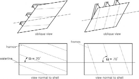
(1) In the case of transversely‐framed plating ( ≥ °, see Fig 2.3), the net thickness is given
× × × (mm)
(2) In the case of longitudinally‐framed plating ( ≤ °), when ≥ , the net thickness is given
× × ×
(3) In the case of longitudinally‐framed plating ( ≤ °, see Fig 2.3), when , the net thick-
× × ×
(4) In the case of obliquely-framed plating( ° °), linear interpolation is to be where
= smallest angle (deg.) between the chord of the waterline and the line of the first level framing as illustrated in Fig 2.3
![]()
= transverse frame spacing in transversely‐framed ships or longitudinal spacing in lon- gitudinally-framed ships (m)
= ice strengthening region Factor from Table 2.4
= Peak Pressure Factor from Table 2.3
= average patch pressure according to 203. 4 (1) (MPa)
2
= minimum yield stress of the material (N/mm )
= height of design load patch (m), where ≤ in the case of 204. 2
= distance between frame supports, i.e. equal to the frame span as given in 205. 1 (5), but not reduced for any fitted end brackets (m). When a stringer is fitted, the need
not be taken
support.
larger than the distance from the stringer to the most distant frame
Fig 2.3 Shell framing angle
205. Framing
1. General
(1) Framing of Polar class ships are to be designed to withstand the ice loads defined in 203.
(2) The term "framing" refers to transverse and longitudinal local frames, stringers and web frames in the regions of the hull exposed to ice pressure.
(3) The strength of a framing member is dependent upon the fixity that is provided at its supports.
Fixity can be assumed where framing members are either continuous through the support or at- tached to a supporting section with a connection bracket. In other cases, simple support is to be assumed unless the connection can be demonstrated to provide significant rotational restraint.
Fixity is to be ensured at the support of any framing which terminates within an ice‐strength- ened region.
(4) The details of framing member intersection with other framing members, including plated struc-
tures, as well as the details for securing the ends of framing members at supporting sections are to be in accordance with the requirements of each member society.
(5) The design span of a framing is to be determined on the basis of its moulded length. If
brackets are fitted, the span may be reduced in accordance with the usual practice of each
member society. Brackets are to be configured to ensure stability in the elastic and post‐yield response regions.
(6) When calculating the section modulus and shear area of a framing member, net thicknesses of
the web, flange (if fitted) and ing member may include that
attached material
![]()
shell plating are to be used. The shear area of a fram- contained over the full depth of the member, i.e. web
![]()
area including portion of flange, if fitted, but excluding attached shell plating.
(7) The actual net effective shear area, , of a framing member is given by:
2
sin (cm )
where
= height of stiffener including thickness of face plate (mm) (see Fig 2.4)
= net web thickness (mm)
=
= as built web thickness (mm) (see Fig 2.4)
= corrosion deduction (mm) to be subtracted from the web and flange thickness (as specified the Society, but not less than as required by 207. 3).
= smallest angle between shell plate and stiffener web, measured at the midspan of the stiffener. (see Fig 2.4) The angle may be taken as 90 degrees provided the smallest angle is not less than 75 degrees.
(8) When the cross-sectional area of the attached plate exceeds the cross-sectional area of the frame, the actual net effective plastic section modulus, , is given by:
sin 3
sin (cm )
where
, , and are as given in 205. 1 (7) and as given in 204.
= net cross-sectional area of shell plating (cm 2)
= net shell plate thickness (mm) (shall comply with as required by 204. 2)
= height of frame web (mm) (see Fig 2.4)
= net cross-sectional area of frame flange (cm 2)
= height of frame measured to centre of the flange area (mm) (see Fig 2.4)
= distance from mid thickness plane of frame web to the centre of the flange area (mm) (see Fig 2.4)
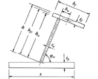
Fig 2.4 Stiffener geometry
(9) When the cross-sectional area of the frame exceeds the cross-sectional area of the attached plate
flange, the plastic neutral axis is located a distance
above the shell plate, given by:
![]()
and the net effective plastic section modulus, , is given by:
sin
cos
sin
(cm3)
(9) In the case of oblique framing arrangement (70 deg > > 20 deg, where is defined as given in 204. 2), linear interpolation is to be used.
2. Transversely framed side structures and bottom structures
(1) The frames in transversely‐framed side structures and bottom structures (i.e. ice strengthening re- gions , and ) are to be dimensioned such that the combined effects of shear and bend- ing do not exceed the plastic strength of the member. Plastic strength is defined as the magni- tude of midspan load that causes the development of a plastic collapse mechanism.
(2) The actual net effective shear area of the frame, culation:
is shall not be less than the following cal-
× × × × × ×
(cm2)
where
= length of loaded portion of span
= lesser of and (m)
= main frame span (m)
= height of design ice load patch according to 203. 3 (1) or (2) (m)
= main frame spacing (m)
= ice strengthening region Factor from Table 2.4
= Peak Pressure Factor from Table 2.3
= average pressure within load patch according to 203. 4 (1) (MPa)
= minimum yield stress of the material (N/mm 2)
(3) The actual net effective plastic section modules of the frame, is shall not be less than the following calculation(where is to be the greater calculated on the basis of following two load conditions). The parameter in the equation reflects the two conditions:
(a) ice load acting at the midspan of the main frame.
(b) ice load acting near a support.
3
× × × × × × × (cm )
where
, , , , , ,
= maximum of
and , are given in
= 1 for framing with one simple support outside the ice strengthened regions
= 2 for framing without any simple supports
![]()
: required shear area(cm 2) for main frame according to
(2) 2
with
as given in 205. 1 (8)
= 0.0 when the frame is arranged with end bracket
3
= sum of individual plastic section modulus of flange and shell plate (cm
=
= flange breadth (mm) (see Fig 2.4)
= net flange thickness (mm)
2
= the fitted net shell plate thickness effective width of shell plate flange (mm)
= plastic section modulus of transverse frame (cm ) (calculated according to
205. 1 (8))
(4) The scantlings of the main frame are to meet the requirements of Par 5.
3. Side longitudinals (longitudinally framed ships)
(1) Side longitudinals are to be dimensioned such that the combined effects of shear and bending do not exceed the plastic strength of the member. Plastic strength is defined as the magnitude of midspan load that causes the development of a plastic collapse mechanism.
(2) The actual net effective shear area of the side ing calculation :
longitudinal is shall not be less than the follow-
× × × ×
(cm2)
where
= Ice strengthening region Factor from Table 2.4
= Peak Pressure Factor from Table 2.3
= average pressure within load patch according to 203. 4 (1) (MPa)
′
′
= height of design ice load patch from 203. 3 (1) or (2) (m)
= main frame spacing (m)
if ′
′
= longitudinal design span as given 205.1 (5)
2
= minimum yield stress of the material (N/mm
(3) The actual net effective plastic section modulus of not be less than the following calculation :
the plate/stiffener combination, is shall
× × × × ×
(cm3)
where
and are as given
![]()
2
= required shear area for longitudinal as given in (2) (cm )
2
= actual net effective shear area of longitudinal as given in (7) (cm )
as given in (8)
(4) The scantlings of the longitudinals are to meet the requirements of Par 5.
4. Web frame and stringers
(1) Web frames and stringers are to be designed to withstand the ice load patch as defined in 203.
The load patch is to be applied at locations where the capacity of these members under the combined effects of bending and shear is minimized.
(2) Web frames and stringers are to be dimensioned such that the combined effects of shear and
bending do not exceed the limit state(s) defined by each member society. Where these members form part of a structural grillage system, appropriate methods of analysis are to be used. Where the structural configuration is such that members do not form part of a grillage system, the ap- propriate peak pressure factor ( ) from Table 2.3 is to be used. Special attention is to be
paid to the shear capacity in way of lightening holes and cut‐outs in way of intersecting members.
(3) The scantlings of web frames and stringers are to meet the requirements of Par 5.
5. Structural stability
(1) To prevent local buckling in the web, the ratio of web height ( ) to net web thickness ( ) of any framing member is not to exceed:
For flat bar sections: ≤
For bulb, tee and angle sections: ≤
where
= web height
= net web
= minimum yield stress of the material (N/mm2 )
(2) Framing members for which it is not practicable to meet the requirements of (1) (e.g. stringers or deep web frames) are required to have their webs effectively stiffened. The scantlings of the web stiffeners are to ensure the structural stability of the framing member. The minimum net web thickness for these framing members is given by the following equation:
(mm)
where
= net web thickness
= web height of stringer / web frame (mm) (see Fig 2.5)
= height of framing member penetrating the member under consideration (0 if no such framing member) (mm) (see Fig 2.5)
= spacing between supporting structure oriented perpendicular to the member under con- sideration (mm) (see Fig 2.5)
= minimum yield stress of the material (N/mm2 )
![]()
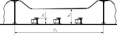
Fig 2.5 Parameter definition for web stiffening
(3) In addition, the following is to be satisfied:
≥
where
2
= minimum upper yield stress of the shell plate in way of the framing member (N/mm )
= net thickness of the web
thickness of the shell plate in way the framing member
(4) To prevent local flange buckling of welded profiles, the following are to be satisfied:
(a) The flange width ( ) shall not be less than five times the net thickness of the web (
).
≤
where
= net thickness of
2
= minimum upper yield stress of the material (N/mm
206.
Plated structures
1. Plated structures are those stiffened plate elements in contact with the hull and subject to ice loads.
These requirements are applicable to an inboard extent which is the lesser of:
(1) web height of adjacent parallel web frame or stringer; or
(2) 2.5 times the depth of framing that intersects the plated structure
2. The thickness of the plating and the scantlings of attached stiffeners are to be such that the degree of end fixity necessary for the shell framing is ensured.
3. The stability of the plated structure is to adequately withstand the ice loads defined in 203.
207.
Corrosion/abrasion additions and steel renewal
1. Effective protection against corrosion and ice‐induced abrasion is recommended for all external sur- faces of the shell plating for all Polar ships.
2. The values of corrosion/abrasion additions, , to be used in determining the shell plate thickness for each Polar Class are listed in Table 2.5.
3. Polar ships are to have a minimum corrosion/abrasion addition of mm applied to all internal structures within the ice‐strengthened regions, including plated members adjacent to the shell, as
well as stiffener webs and flanges.
4. Steel renewal for ice strengthened structures is required when the gauged thickness is less than mm.
![]()
Table 2.5 Corrosion/Abrasion additions for shell plating
Ice strengthening region | ts (mm) | |||||
With Effective Protection | Without Effective Protection | |||||
PC1 ‐ PC3 | PC4 & PC5 | PC6 & PC7 | PC1 ‐ PC3 | PC4 & PC5 | PC6 & PC7 | |
Bow; Bow Intermediate Icebelt | 3.5 | 2.5 | 2.0 | 7.0 | 5.0 | 4.0 |
Bow Intermediate Lower; Midbody & Stern Icebelt | 2.5 | 2.0 | 2.0 | 5.0 | 4.0 | 3.0 |
Midbody & Stern Lower; Bottom | 2.0 | 2.0 | 2.0 | 4.0 | 3.0 | 2.5 |
208. Materials
1. Plating materials for hull structures are to be not less than those given in Tables 2.7 and 2.8 based on the as built thickness of the material, the Polar ice class notation assigned to the ship and the Material Class of structural members given in 2.
2. Material classes specified in Pt 2, Ch 1 of the Rules for the Classification of Steel Ships, Table 3.1.4 are applicable to polar ships regardless of the ship’s length. In addition, material classes for weather and sea exposed structural members and for members attached to the weather and sea exposed shell plating of polar ships are given in Table 2.6. Where the material classes in Table 2.6, and those in Pt 2, Ch 1 Table 3.1.4 of the Rules for the Classification of Steel Ships differ, the higher material class is to be applied.
3. Steel grades for all plating and attached framing of hull structures and appendages situated below
the level of 0.3 m below the lower waterline, as shown in
Ch 1, Table 3.1.9 of the Rules for the Classification
Fig 2.7, are to be obtained from Pt 2 of Steel Ships based on the Material
Class for Structural Members in Table 2.7, above, regardless of Polar Class.
4. Steel grades for all weather exposed plating of hull structures and appendages situated above the level of 0.3 m below the lower ice waterline, as shown in Fig 2.6, are to be not less than given in Table 2.8.
5. Steel grades for all inboard framing members attached to weather exposed plating are to be not less than given in Table 2.8. This applies to all inboard framing members as well as to other contiguous inboard members (e.g. bulkheads, decks) within 600 mm of the exposed plating.
![]()
6. Castings are to have specified properties consistent with the expected service temperature for the cast component.
![]()
Table 2.6 Material classes for structural members of polar ships
Structural Members | Material Class |
Shell plating within the bow and bow intermediate icebelt hull regions (B, BIi) | II |
All weather and sea exposed SECONDARY and PRIMARY, as defined in Pt 2, Ch 1 Table 3.1.4 of the Rules for the Classification of Steel Ships, structural members outside amidships | I |
Plating materials for stem and stern frames, rudder horn, rudder, propeller nozzle, shaft brackets, ice skeg, ice knife and other appendages subject to ice impact loads | II |
All inboard framing members attached to the weather and sea‐exposed plating including any contiguous inboard member within 600 mm of the shell plating | I |
Weather‐exposed plating and attached framing in cargo holds of ships which by nature of their trade have their cargo hold hatches open during cold weather operations | I |
All weather and sea exposed SPECIAL, as defined in Pt 2, Ch 1 Table 3.1.4 of the Rules for the Classification of Steel Ships, structural members within from FP | II |
Table 2.7 Steel grades for weather exposed plating
Thickness, (mm) | Material Class | I | Material Class | II | Material Class | III | ||||||||
PC1‐5 | PC6&7 | PC1‐5 | PC6&7 | PC1‐3 | PC4&5 | PC6&7 | ||||||||
MS | HT | MS | HT | MS | HT | MS | HT | MS | HT | MS | HT | MS | HT | |
B | AH | B | AH | B | AH | B | AH | E | EH | E | EH | B | AH | |
B | AH | B | AH | D | DH | B | AH | E | EH | E | EH | D | DH | |
D | DH | B | AH | D | DH | B | AH | E | EH | E | EH | D | DH | |
D | DH | B | AH | D | DH | B | AH | E | EH | E | EH | D | DH | |
D | DH | B | AH | E | EH | D | DH | E | EH | E | EH | E | EH | |
D | DH | B | AH | E | EH | D | DH | E | EH | E | EH | E | EH | |
D | DH | D | DH | E | EH | D | DH | F | FH | E | EH | E | EH | |
E | EH | D | DH | E | EH | D | DH | F | FH | E | EH | E | EH | |
E | EH | D | DH | E | EH | D | DH | F | FH | F | FH | E | EH | |
Notes : 1) Includes weather‐exposed plating of hull structures and appendages, as well as their outboard fram- ing members, situated above a level of 0.3 m below the lowest ice waterline. 2) Grades D, DH are allowed for a single strake of side shell plating not more than 1.8 m wide from 0.3 m below the lowest ice waterline. | ||||||||||||||
![]()
Table 2.8 Steel grades for inboard framing members attached to weather exposed plating
Thickness , mm | PC1 ‐ PC5 | PC6 & PC7 | ||
MS | HT | MS | HT | |
≤ | B | AH | B | AH |
≤ | D | DH | B | AH |
≤ | D | DH | D | DH |
≤ | E | EH | D | DH |
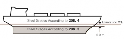
Fig 2.6 Steel grade requirements for submerged and weather exposed shell plating
209. Longitudinal strength
1. Application
Ice loads need only be combined with still water loads. The combined stresses are to be compared
against permissible bending and shear stresses at different locations along the ship’s length. tion, sufficient local buckling strength is also to be verified.
2. Design vertical ice force at the bow
The design vertical ice force at the bow, , is to be taken as:
In addi-
min
(MN)
where
sin
(MN)
= indentation parameter =
(MN)
(1) for the case of a blunt bow form
tan
(2) for the case of wedge bow form ( deg and the above simplifies
tan
tan
![]()
(MN/m)
![]()
Fig
= Longitudinal Strength Class Factor from Table 2.2
= bow shape exponent which best describes the waterplane (see
= 1.0 for a simple wedge bow form
= 0.4 to 0.6 for a spoon bow form
= 0 for a landing craft bow form
2.7 and 2.8)
stem angle to be measured between the horizontal axis and the stem tangent at the upper ice waterline (deg) (buttock angle as per Fig 2.2 measured on the centerline) waterline angle measured in way of the stem at the upper ice waterline (UIWL) [deg] (see Fig 2.2)
= ship moulded breadth (m)
= bow length used in the equation (m) (see Fig 2.7 and
= ship displacement (kt), where
= ship waterplane area (m2)
min
10 kt
= Flexural Failure Class Factor from Table 2.2
Where applicable, draught dependent quantities are to be determined at the waterline corre- sponding to the loading condition under consideration.
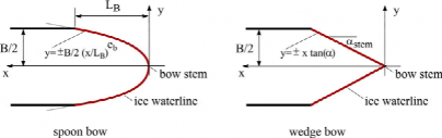
Fig 2.7 Bow shape definition
![]()
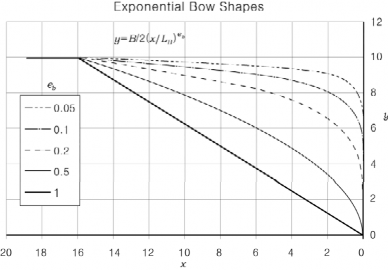
Fig 2.8 Illustration of effect on the bow shape for = 20 and =16
3. Design vertical ice shear force
(1) The design vertical ice shear force, , along the hull girder is to be taken as: (MN)
where
= longitudinal distribution factor to be taken as follows:
(a) Positive shear force
between the aft end of and from aft between from aft and the forward end of
at the aft end of
between and from aft between from aft and the forward end
Intermediate values are to be determined by linear interpolation
(2) The applied vertical shear stress, , is to be determined along the hull girder in a similar man- ner as in Pt 2 Ch 3, 402. 2 of the Rules for the Classification of Steel Ships of the Rules by substituting the design vertical ice shear force for the design vertical wave shear force.
4. Design vertical ice bending moment
(1) The design vertical ice bending moment, , along the hull girder is to be taken as:
sin (MN-m)
where
= ship length (rule length as defined in Pt 2, Ch 1, 102 of the Rules for the Classification of Steel Ships. of the Rules) but measured on the upper ice water- line (m)
![]()
= stem angle to be measured between the horizontal axis and the stem tangent at the up-
![]()
per ice waterline (deg)
= design vertical ice force at the bow (MN)
= longitudinal distribution factor for design vertical ice bending moment to be taken as follows:
at the aft end of
between and from
aft at from aft at the forward end of
Intermediate values are to be determined by linear interpolation
Where applicable, draught dependent quantities are to be determined at sponding to the loading condition under consideration.
(2) The applied vertical bending stress, , is to be along the hull
the waterline corre-
girder in a similar
manner as in Pt 2, Ch 1, 402. 1 of the Rules for the
Classification
of Steel Ships. of
the Rules, by substituting the design vertical ice bending moment for the design vertical wave
bending moment. The ship still water bending moment is to be taken as the maximum sag- ging moment.
5. Longitudinal strength criteria
(1) The strength criteria provided in Table 2.9 are to be satisfied. ceed the permissible stress.
The design stress is not to ex-
Table 2.9 Longitudinal strength criteria
Failure Mode | Applied Stress | Permissible Stress (when ≤ | Permissible Stress (when |
Tension | × | × | |
Shear | |||
Buckling | for plating and for web plating of stiffeners for stiffeners | ||
where
2
= applied vertical bending stress (N/mm
) 2
2
= minimum upper yield stress of the material (N/mm )
= ultimate tensile strength of material (N/mm2 )
= critical buckling stress in compression, according to
Pt Classification of Steel Ships (N/mm2)
3, Ch 4 of the Rules for the
the
= critical buckling stress in shear, according to Pt 3, Ch 4 of the Rules for Classification of Steel Ships (N/mm2)
210. Stem and stern frames
The stem and stern frame are to be designed according to the PC6/PC7 ships requiring IA SUPER/IA equivalency, the stem and
![]()
1 and 407. of the Rules may need to be additionally considered.
requirements of the Society. For stern requirements of Ch 1, 406.
![]()
211. Appendages
1. All appendages are to be designed to withstand forces appropriate for the location of their attach- ment to the hull structure or their position within a ice strengthening region.
2. Load definition and response criteria are to be determined by each member society.
212. Local details
1. For the purpose of transferring ice loads to supporting structure (bending moments and shear forces), local design details are to comply with the requirements of each member society.
2. The loads carried by a member in way of cut‐outs are not to cause instability. Where necessary, the structure is to be stiffened.
213. Direct calculations
1. Direct calculations are not to be utilized as an alternative to the analytical procedures prescribed in this unified requirement.
2. Where direct calculation is used to check the strength of structural systems, the load patch speci- fied in 203. is to be applied.
214. Welding
1. All welding within ice‐strengthened regions is to be of the double-sided continuous type.
2. Continuity of strength is to be ensured at all structural connections.